Tidal Current Turbine
¨C¨C¨C¨C Analysis by OpenFOAM
Tidal current
power is one of the most potential resources for future electricity generation,
corresponding investigation is attracted increasing interest. The objective of
this research is to study the hydrodynamic behavior of a turbine operating in
the wake. The optimization of turbine arrangement in a tidal farm is also of
our consideration. Then Estimate the output of the power plant in a tidal
period. To achieve these goals, both the fully resolved geometrical method and
the simplified turbine model are developed.
Fully resolved
geometrical method
For single turbine
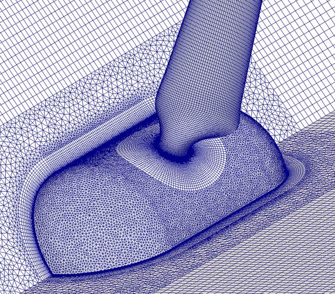
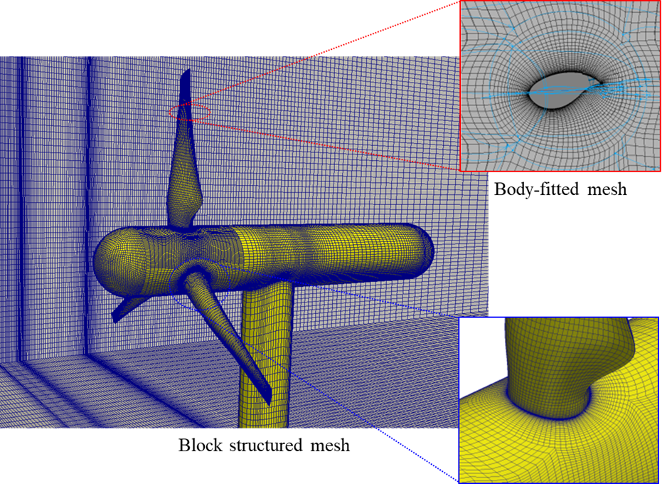
Fig. 1 Left,
hybrid mesh (Multiple Reference Frame
method); right, structured mesh (Sliding Mesh method).
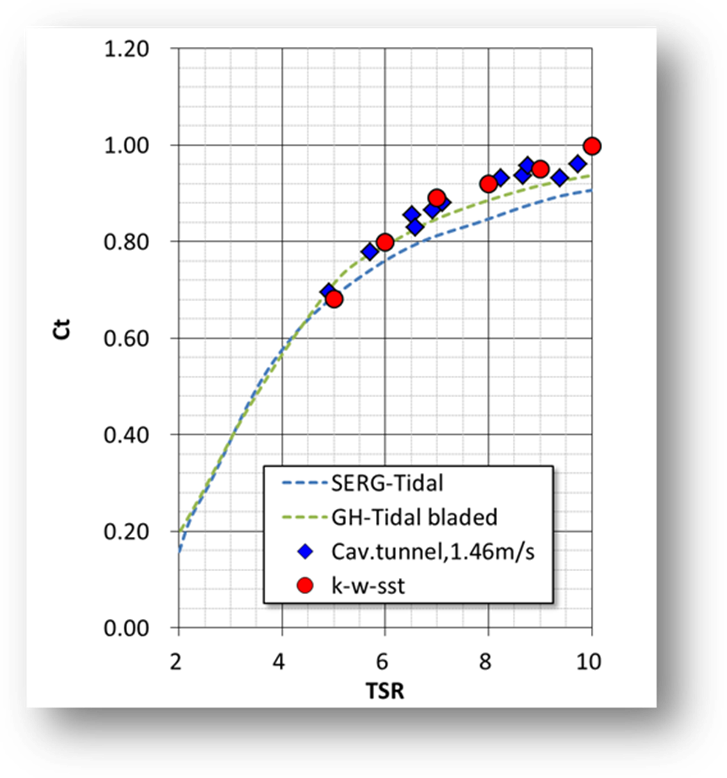
(a) 5-degree
pitch angle,
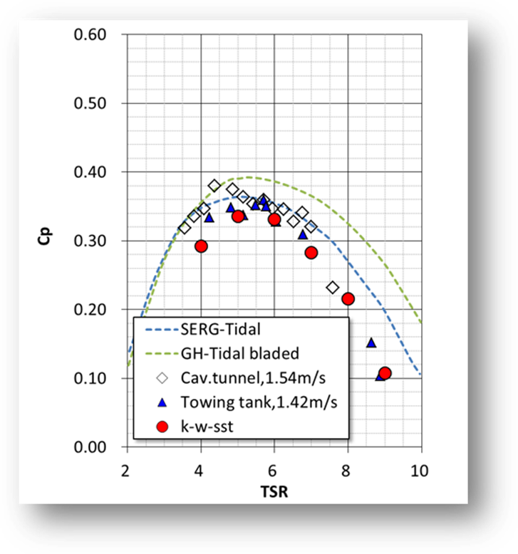
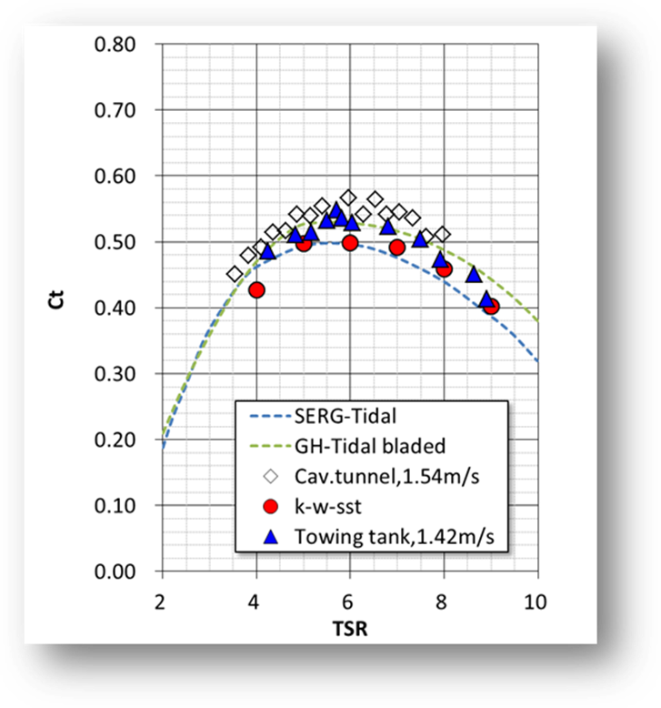
(b) 10-degree
pitch angle,
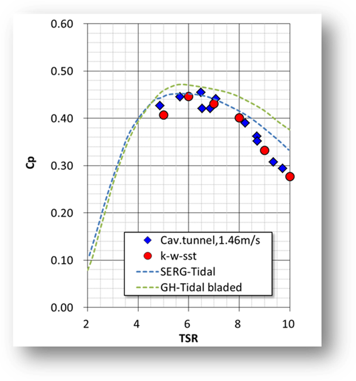
Fig.3
Thrust and torque coefficients.
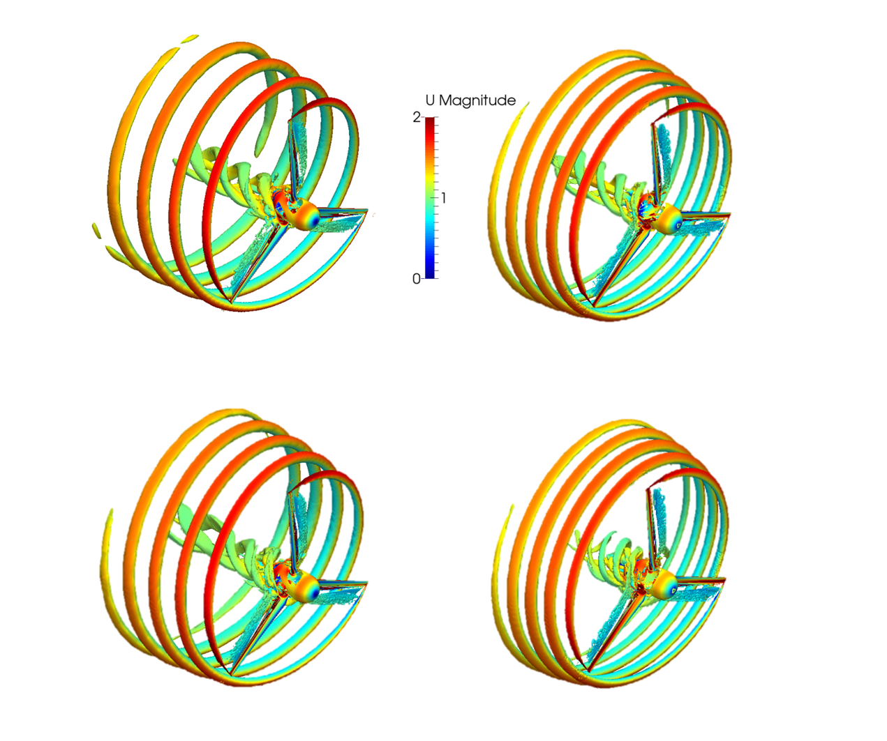
Fig.4
Vortex structure for TSR=5, 6, 8, 9.
Simplified Rotor Model
AL
(actuator line) model with URANS
In this study, an efficient numerical method for predicting
the wake interference of multiple turbines is presented. To save the cost, the
(actuator line) AL model instead of the fully resolved turbine are developed.
The URANS equations are solved to model the turbulent flow behind the rotor.
Three turbulence models, original k−¦Ř,
k−¦Ř−SST and corrected k−¦Ř model are implemented for
comparison. The AL model with corrections to volume force calculation is
introduced to represent the rotors. The moving least square (MLS) immersed
boundary (IB) method considering the wall functions is proposed to study the
hub and tower effect. The local mesh refinement is applied at the regions
containing high gradient. The combination of AL model and IB method is highly
efficient for case-studies of different configurations of multiple turbines.
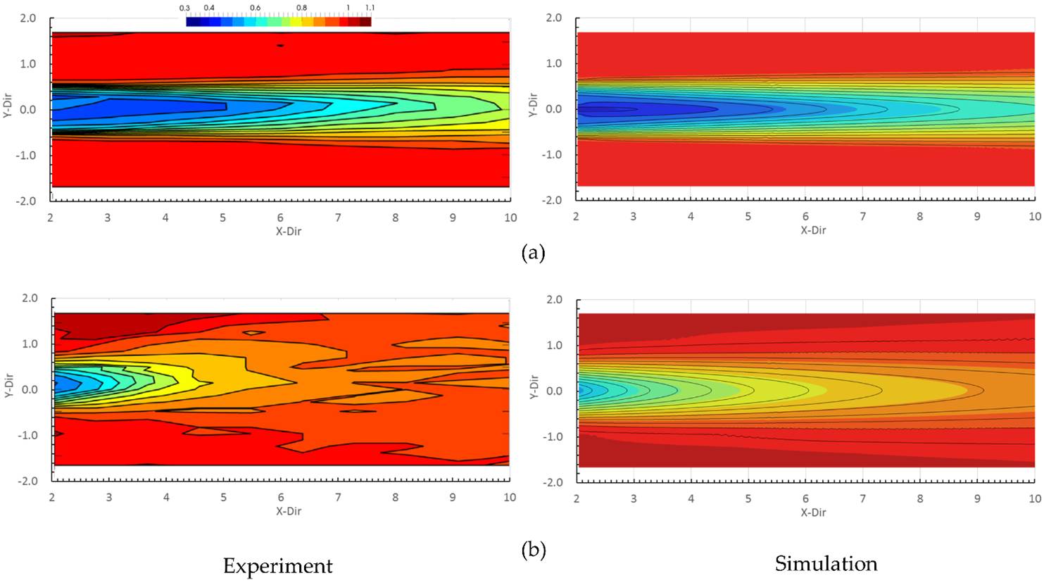
Fig.6 Comparison
of experimental and numerical results of velocity for single IFREMERˇŻs rotors.
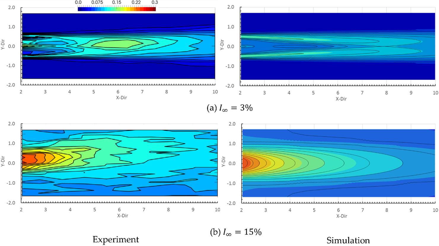
Fig.6 Comparison
of experimental and numerical results of turbulence intensity for single IFREMERˇŻs
rotors.
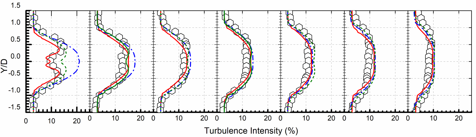
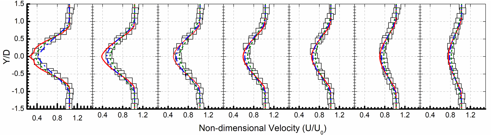
Fig.5 TI
profiles and velocity deficit along the rotor center for the IFREMERˇŻs double
rotors case TI=3% and 4D spacing. ⬡: TI from the experiment, ˇő: ![]() from the experiment.
from the experiment.
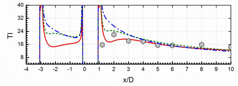
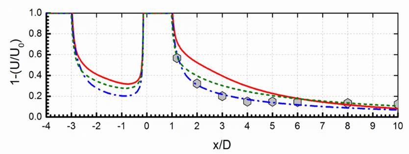
Fig.6
Velocity deficit and turbulence intensity along the rotor center.
ACL
(actuator line) model with LES
Terrain
Effect
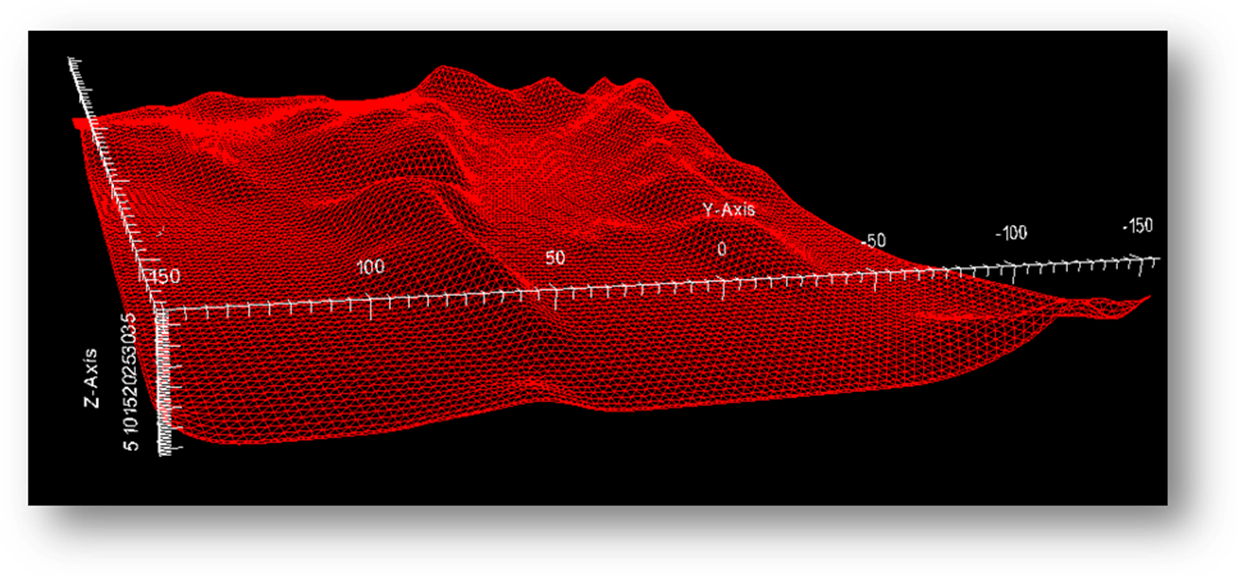
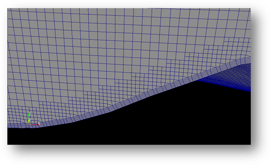
Fig.7 Terrain-fitted
mesh generated by SnappyHexMesh in OpenFOAM.
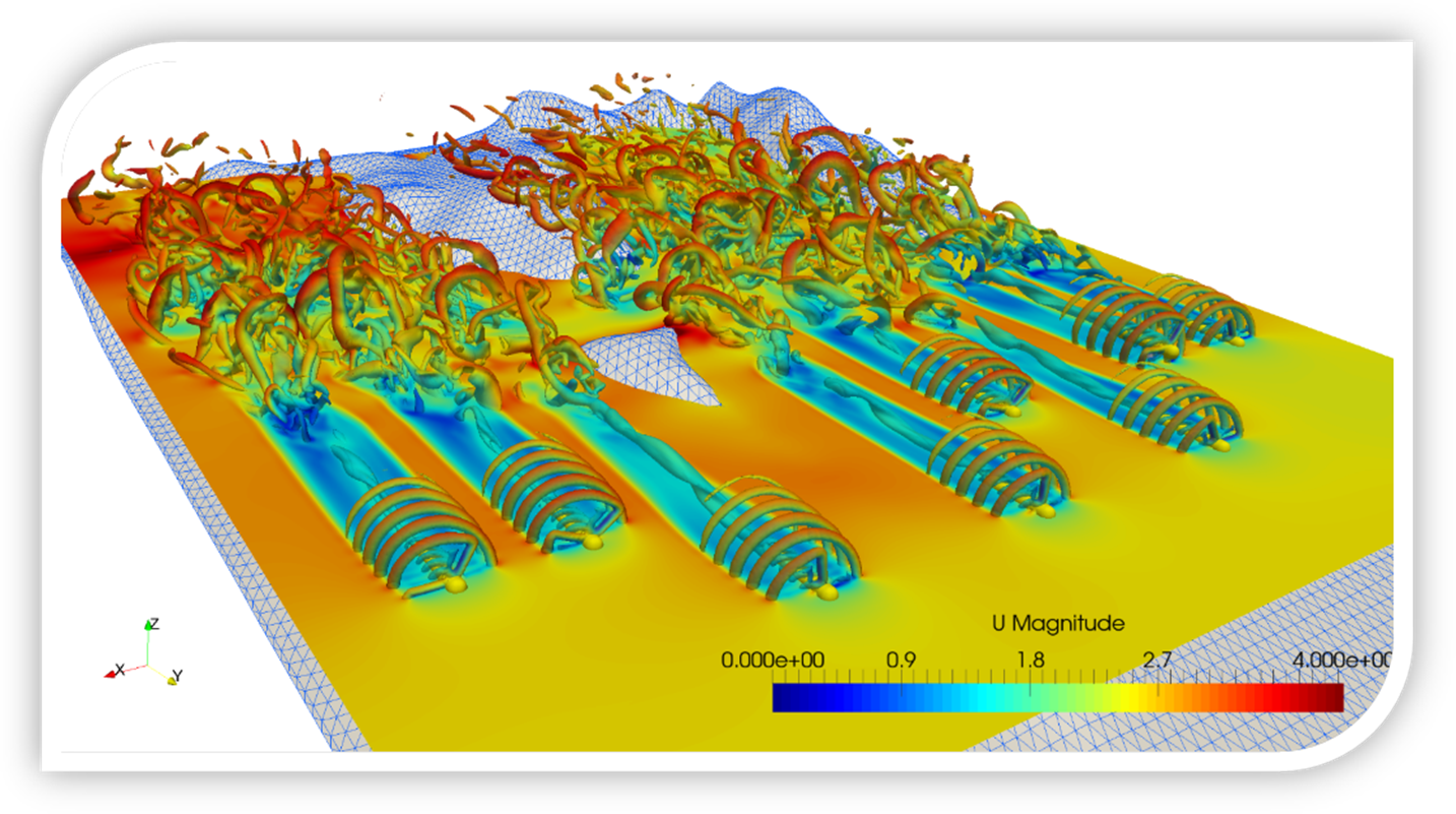
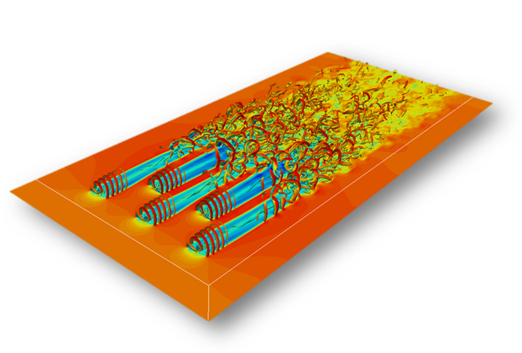
Fig.8 Tidal
farm simulation considering terrain effect, by our AL-IB solver.
Adaptive
Mesh Refinement
The dynamically cell-based mesh refinement in OpenFOAM
is utilized to resolve the regions containing solid surface and large velocity
gradient. The
regions adjacent to the support structure and blades as well as tip vortex are
under refining.
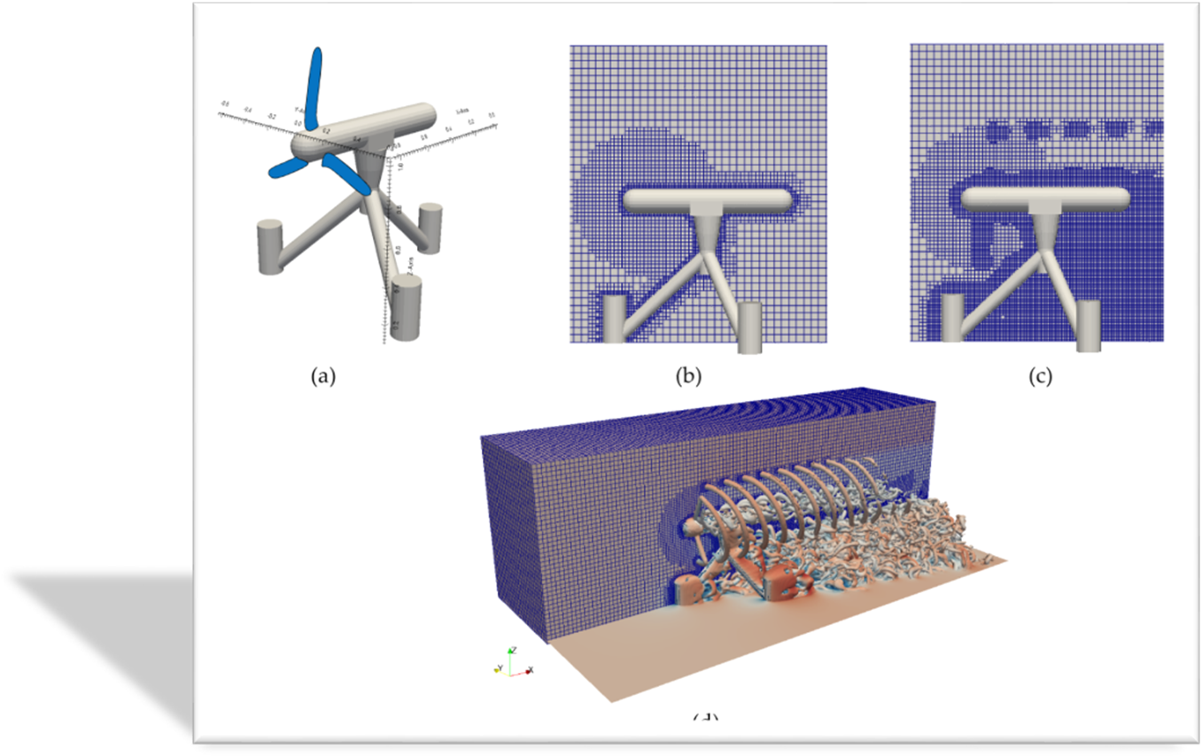
Fig. 9 A
LES simulation by present AL-IB solver. (a) Sketch of a gravity based tidal
turbine, (b) initial mesh before the start of the simulation, (c) instantaneous
adaptive mesh during the simulation, (d) vortex structure.
Reference
C. Liu*, C. Hu, Simulation of Multiple Tidal Turbines
with Actuator line - Immersed Boundary Method, submitted.
C. Hu, C. Liu, CFD Simulation and experimental
measurement of the wake of a horizontal tidal current turbine, The 3rd
Asian Wave and Tidal Energy Conference, Singapore, 2016.
C. Liu, C. Hu, Numerical Prediction of the Hydrodynamic
Performance of Horizontal Tidal Turbines, ASME 34th International
Conference on Ocean, Offshore and Arctic Engineering, St. John's,
Canada, 2015.
C. Hu, C. Liu, Development and Validation of
RANS CFD Model for Hydrodynamic Prediction of a Horizontal Tidal Current
Turbine, Proceedings of the 11th European Wave and Tidal Conference,
Nantes, France, 2015.
C. Liu, C. Hu, Numerical Simulation of a Horizontal Axis
Tidal Turbine Using OpenFOAM, Conference
proceedings, the Japan Society of Naval Architects and Ocean Engineers (ČŐ±ľ´¬˛°şŁŃóą¤Ń§»áÖvŃÝ»áŐ“ÎÄĽŻ), 19:
503-504, Nagasaki, Japan, 2014.